8051 Microcontrollers are widely used by students, learners, hobbyists and professionals. Objective of this tutorial is to provide information about accessing LED connected directly to GPIO pin of 8051 microcontrollers. Information provided in this tutorial is applicable to using any GPIO pin of 8051 microcontrollers for output purpose.
Let us consider one LED is connected at pin 1 of 8051 Microcontroller. Any 8051 microcontrollers for example AT89C52 Microcontroller from Atmel can be used. Pin # 1 is P1.0 of 8051 microcontrollers.P1.0 is GPIO Port number P1 and bit 0, it is routed to pin # 1 of microcontroller.
Figure 1: 8051 Microcontroller and Pins
8051 Microcontroller has four ports, named as P0, P1, P2 and P3. For more details of each port of 8051 and associated pins, refer microcontroller document from silicon vendor website. For example, Atmel or NXP website. Refer Figurer 1.
In following example, LED is connected to P1.0 in such a way that Cathode is towards P1.0 and +5V is applied to Anode of LED. Refer Figure 2
Figure 2: LED connected with 8051 Microcontroller
In Figure 2, one Microcontroller of 8051 series is connected to LED at Port 1 and Pin 1. LED is connected with +5V through 220-ohm resistor. Crystal OSC of 12 MHz are connected to provide clock to the Microcontroller. Any 8051 board can also be used for this experiment.
Various 8051 board are available on Amazon kind of websites, which can be purchased and used for this experiment. LED may be connected to any other pin, for exact connection, board document should be referred. According the LED connection with Microcontroller pin, there will be requirement for modification in code. Refer source code provided in this document.
Glowing or switch on LED
LED will glow if current will pass through it. If P.0 is grounded, then current will flow from LED and as a result LED will start glowing.
Figure 3: LED glowing, as P.0 is grounded
Refer figure 3, P1.0 can be grounded, by writing 0 to P1.0. This can be done by Coding.
Below is the C Program Statement
P1.0 =0; (As per Keil IDE)
Or in assembly language
CLR P1.0
Switching Off LED
Now if we want to switch off LED then P1.0 should not be grounded, as we don’t want current to flow through LED. So,Port P1.0 should be HIGH.
Figure 4: Switch OFF LED, P1.0 is HIGH
Hence, as a result LED will be OFF. Refer Figure 4.
This can be achieved by coding. Below is the C Program Statement …
P1.0 =1; (As per Keil IDE)
Or in assembly language
SETB P1.0
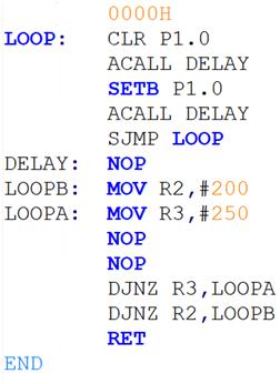
Program to Blink LED
Now we are in the position to write a program for blinking of LED. Below are the assembly and C program for blinking of LED.
C Language Program
Assembly Language Program