The Microcontroller can serve several devices. The Interrupt is the method to indicate the microcontroller by sending it an interrupt signal. After receiving an interrupt, the microcontroller interrupts what ever it is doing and serves the device. The program associated with the interrupt is called the interrupt service and routine (ISR).
There must be interrupt service routine (ISR), or interrupt Handler. When an interrupt is invoked, the microcontroller runs the interrupt service routine. For every interrupt, there is a fixed location set aside to hold the addresses of ISRs is called. todo
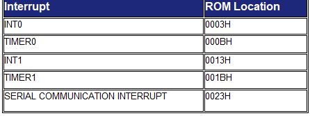
Interrupt Vector Table
Step in executing an Interrupt:
1) It finish the instruction it is executing and saves the address of the next instruction (PC) on the stack.
2) It also saves the current status of all the interrupt internally.
3) It Jumps to a fixed location in memory called the interrupt vector table that holds the address of the interrupt service routine.
4) The microcontroller gets the address of the ISR from the interrupt vector and jumps to it. It starts to execute the interrupt service subroutine until it reaches the last instruction of the subroutine.
5) Upon executing the RETI instruction ,the microcontroller returns to the Place where it was interrupt.
Interrupt Enable Register (EA)
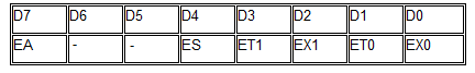
EA IE.7 Disable all interrupts .
If EA= 0 no interrupt is acknowledged If
EA=1 , each interrupt source is individually Enable or disable
By setting or clearing the enable or disable
ES IE.4 Enable or disable the serial port interrupt
ET1 IE.3 Enable or disable Timer 1 overflow interrupt
EX1 IE.2 Enable or disable external interrupt 1
ET0 IE.1 Enable or disable Timer 0 overflow interrupt.
EX0 IE.0 Enable or disable external interrupt 0.
Enabling and disabling Interrupts
Upon reset all interrupts are disable, meaning that known will be responded to by the microcontroller if they are activated. The Interrupt must be enabled by software in order for microcontroller to respond to them there is a register called IE that is responsible for enabling and disabling the interrupts.
Steps in Enable an Interrupt
To enable an interrupt an interrupt we take following steps.
1.Bit D7 of the IE Register must to set to high to allow the rest of register to take effect.
2.If EA=1, interrupts are enable and will to responded to if this corresponding bits in IE are High. If EA=1, No Interrupt will be responeded.
Programming External Hardware Interrupts
The 8051 has two external hardware interrupts PIN 12 (P3.2) and Pin 13 (P3.3) of the 8051, designated as INT0 and INT1 are used as external hardware interrupts. Upon activation of these pins, the 8051 gets interrupts in what ever it is doing and jumps to the vector table to perform the interrupt service routine
Type of Interrupt
1)Level-Triggered Interrupt
2)Edge -Triggered Interrupt
Level-Triggered Interrupt
In this mode, INT0 and INT1 are normally high and if the low level signal is applied to them ,It triggers the Interrupt. Then the microcontroller stops and jumps to the interrupt vector table to service that interrupt .This is all the Level Triggered or Level -Activated interrupt and is the default mode/reset of 8051.
Edge -Triggered Interrupt
Upon reset 8051 makes INT0 and INT1 low l Level-Triggered Interrupt. To make them Edge -Triggered Interrupt, we must program the bits of the TCON Register. The TCON register holds among other bits and IT0 and IT1 flags bit the determine level- or edge triggered mode. Of the hardware interrupt IT0 and IT1 and bits D0 and D2 of the TCON Register Respectively. In this Section, we have discuss only INT0 and INT1 External Hardware Interrupts.
In this example, The Steeper Motor will Rotate when External Interrupt INT1 will Trigger.

Software
This program is written in assemble language
$mod51
ORG 00H
LJMP Main
;ISR for hardware interrupt INT1 to Rotate Steeper Motor
MOV A, #88H ; 10001000B
LOOP:
MOV P1, A
ACALL DELAY
RR A ; ROTATE BITS
SJMP LOOP
DELAY:
MOV TMOD, #01H
MOV TCON, #00H
MOV TL1, #0E0H
MOV TH0, #0B1H
SETB TR0
WAIT: JNB TF0, WAIT
RET
END
;Main Initilazation
ORG 30H
MAIN: MOV IE,#1000 0100 ;Enable External INT1
Here: SJMP HERE
END