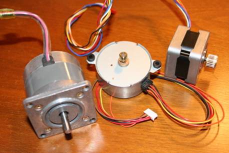
A Stepper Motor is widely used device in position control task. A Stepper Motor is widely used for translates electrical pulses in to mechanical movement. Stepper Motor Have a permanent magnet or rotor surrounded by stator.. A Stepper Motor is a brushless synchronous electric motor that can divide a full rotation into a large number of steps.
In Most of Cases 16 x 1 LCD is available without Auxiliary Controller. Means as you see only HD44780 Controller at Back Side. In this section we discuss LCD 16 x 1 with no Auxiliary Controller.
STEPPER MOTOR CHARACTERISTICS
Stepper motors are constant-power devices (power = angular velocity x torque). As motor speed increases, torque decreases. The torque curve may be extended by using current limiting drivers and increasing the driving voltage. Steppers exhibit more vibration than other motor types, as the discrete step tends to snap the rotor from one position to another. This vibration can become very bad at some speeds and can cause the motor to lose torque. The effect can be mitigated by accelerating quickly through the problem speed range, physically damping the system, or using a micro-stepping driver. Motors with greater number of phases also exhibit smoother operation than those with fewer phases.
ADVANTAGES OF STEPPER MOTOR
The motor's position can be controlled precisely, without any feedback mechanism or Stepper Motor are allow to control any motion with High Precision by Counting the number of steps applied to motor or we can say by giving appropriate delays between successive steps we can easily control speed and even direction of Stepper Motor.
TYPES OF STEPPER MOTOR
1.Unipolar Stepper Motor
2.Bi-Polar Stepper Motor
3.Variable Reluctance Stepper Motor
UNIPOLAR STEPPER MOTOR
A unipolar stepper motor has logically two windings per phase, one for each direction of current. Since in this arrangement a magnetic pole can be reversed without switching the direction of current, the commutation circuit can be made very simple (eg. a single transistor) for each winding. Typically, given a phase, one end f each winding is made common: giving three leads per phase and six leads for a typical two phase motor. Often, these two phase commons are internally joined, so the motor has only five leads.
BIPOLAR STEPPER MOTOR
Bipolar Stepper Motor have two winding called a and b.These motors have exact four wire. Bipolar motors have logically a single winding per phase. The current in a winding needs to be reversed in order to reverse a magnetic pole, so the driving circuit must be more complicated, typically with an H-bridge arrangement. There are two leads per phase, none are common
VARIABLE RELUCTANCE STEPPER MOTOR
The motor which do not have permanent magnetic PM rotor is called Variable Reluctance Stepper Motor. The motor also have two winding and having one common terminal for that.
IDENTIFY LEADS (WIRES) OF STEPPER MOTOR
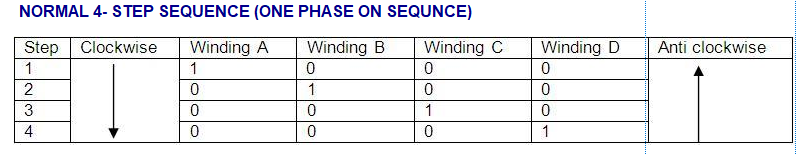
Uni Polar Stepper Motors are commonly used. Because it does not require H-Bridge for interfacing with Microcontroller Like in Bipolar SMs .Use an Ohm Meter to Measure the Resistance of Leads. One way to distinguish common wire from a coil-end wire is by measuring the resistance. Resistance between common wire and coil-end wire is always half of what it is between coil-end and coil-end wires. This should identify which COM is lead. After identifying the Common lead is connected to Vcc. Stepper Motor datasheet can also help you Identify Leads. Other method pencil Cell (1.5V Power Supply or voltage above excitation SM) is used to differentiate among four wires to interface stepper motor in sequence with Microcontroller (with Driver Circuitry). Just connect one COM wire with positive end of cell and connect other four wires one by one to negative side of cell. When SM complete its rotation either clock wise or anti clock completely means you identify SM Lead 1a,1b,2a,2b. So when the next electromagnet is turned on and the first is turned off, the gear rotates slightly to align with the next one, and from there the process is repeated. Each of those slight rotations is called a "step." In that way, the motor can be turned a precise angle.
APPLICATIONS
Computer-controlled stepper motors are one of the most versatile forms of positioning systems . They are typically digitally controlled as part of an open loop system, and are simpler and more rugged than closed loop servo systems. Industrial applications are in high speed pick and place equipment and multi-axis machine CNC machines often directly driving lead screws or ball screws . In the field of lasers and optics they are frequently used in precision positioning equipment such as linear actuators , linear stages , rotation stages and mirror mounts . Other uses are in packaging machinery, and positioning of valve pilot stages for fluid control systems. Commercially, stepper motors are used in floppy disk drives , flatbed scanners , computer printers , plotters and many more devices.